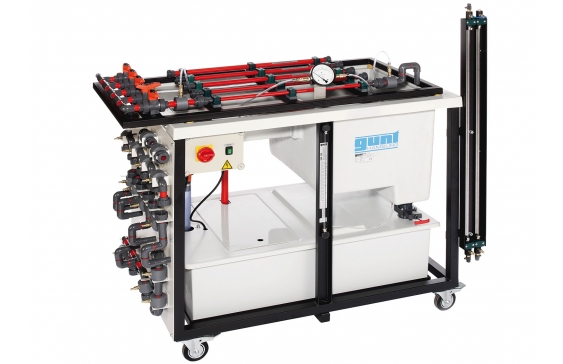
HM 111 Pipe networks

An important task in the construction of pipelines is to determine the pressure and flow rate in complex piping systems. In practice, the calculation of the total pressure losses serves as a foundation for the design of suitable drive units for heating and air conditioning systems, drinking water supply systems and parts of wastewater systems. Knowledge of pressure losses is also used to optimise operation.
HM 111 enables the construction and investigation of various pipe networks, such as parallel and series connections of pipes, their branching and merging, and the study of individual pipes. In analogy to Kirchhoff’s laws of electricity, it is possible to conduct nodal analysis.
The five pre-installed pipe sections on the top of the trainer are connected to pipe networks using the piping elements. Tank, pipes, piping elements and valves and fittings are made entirely of plastic. The individual pipe sections are shut off by ball valves. During the experiments, the pressure losses in various pipes and piping elements are recorded and evaluated.
Two manometers for different measuring ranges are included to measure differential pressure. The flow rate is measured volumetrically.
The trainer has its own water supply. The closed water circuit includes a supply tank with submersible pump.
- structure of various pipe networks
- pressure losses at various piping elements and pipe networks
- closed water circuit with tank and pump
Pump
- power consumption: 250W
- max. flow rate: 9m3/h
- max. head: 7,6m
Pipe network, max. flow rate: 4,8m3/h
Pipe sections, length 700mm each
- 1x: 25×1,9mm
- 2x: 20×1,5mm
- 2x: 16×1,2mm
Twin tube manometers
Tank for water: 180L
Tank for flow rate measurement
- small measuring range: 10L
- large measuring range: 40L
Stopwatch: 1/100s
Measuring ranges
- differential pressure: 1x 0…1bar
- differential pressure with tube manometers: 2x 0…100mbar
230V, 50Hz, 1 phase
230V, 60Hz, 1 phase; 120V, 60Hz, 1 phase
UL/CSA optional
- investigation of different pipe networks
- five pre-installed pipe sections with different diameters
- panel for piping elements
- construction of pipe networks from pipe sections and various piping elements
- calibration of pipe sections
- parallel and series connection of pipe sections
- construction of a closed circular pipeline
- differential pressure measurement with twin tube manometers and differential pressure manometer
- flow rate measurement with measuring tank (can be shut off), stopwatch and level indicator
- recording the calibration curve for pipe sections: pressure loss over flow rate
- pipe sections connected in parallel
- pipe sections connected in series
- combined series and parallel connection
- investigation of a closed circular pipeline
- differential pressure measurement
- pressure losses at various piping elements
