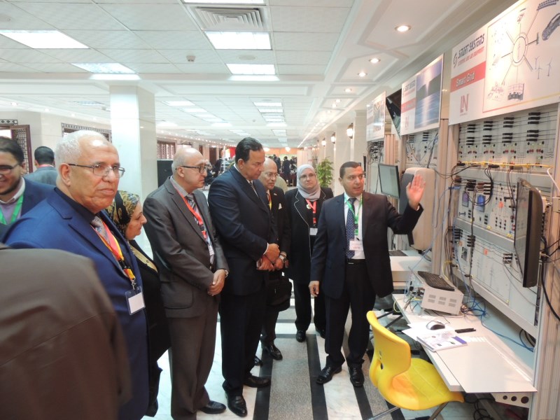
ESG 1 Smart Grid Trainer
ESG 1 Smart Grid Trainer
Electric power distribution
Electrical power at large switching stations is distributed almost exclusively using double busbar systems. These stations incorporate switching matrices for connecting the two busbars, the incoming and outgoing feeder cubicles as well as the measurement fields. The incoming and outgoing feeder cubicles as well as the switching matrices are furnished with circuit breakers and one disconnector for each busbar terminal. For safety reasons, a particular switching logic must be strictly adhered to here. The double busbar model incorporates all functions of practical relevance. Integrated instruments for measuring currents and voltages permit direct analyses of switching operations.
Transmission lines
For your safety, the 380kV transmission lines are investigated and connected at a low-voltage level without detracting from the characteristics of a real high-voltage line. This realistic simulation of a 380-kV transmission line switches over automatically between line lengths of 300 km and 150 km (93.2miles and 186.4miles) once the overlay mask has been put into place. Joint use of several line simulation models connected in parallel or series permits complex networks to be assembled.
Line protection
In practice, medium-voltage and high-voltage networks are equipped with protective mechanisms connected via current and voltage transformers.
The equipment set offers the following benefits
Use of compact, original relays incorporating cutting-edge digital technology
Use of industrial safety relays from prestigious international manufacturers
Monitoring of protective features by means of SCADA (Supervisory Control and Data Acquisition)
A relay test option permits the relays to be checked individually
Investigating complex loads
Experiments on reducing peak loads through measurements with active-current and maximum-demand meters demonstrate how the load on an electricity supply network can be reduced and evenly distributed over a 24-hour period. An analysis of the power supply grid and connected consumers (loads) is necessary for effective use of the measurement techniques involved. Accordingly, each experiment permits a detailed investigation of static, dynamic, symmetric and asymmetric loads.
In this case, a three-phase asynchronous motor coupled with the servo machine test stand is used as a dynamic load. The active and reactive powers (cos-phi for the motor) depend on the motor load and are therefore not constant. The servo machine test stand can be used to drive the asynchronous motor, thereby feeding active power into the three-phase network. Reactive power compensation in alternating voltage networks is designed to reduce undesirable reactive current and resultant reactive power of consumers. In this process, capacitive loads are connected to all inductive loads via a central feed point. The opposing, capacitive reactive power arising here is ideally of the same magnitude as the installed, inductive reactive power. This reduces undesirable reactive currents, and none of the systems needed to supply the reactive current has to be over-dimensioned.

