
HM 120 Losses in pipe elements
In pipes through which water flows, the pipe friction and various deflections cause pressure losses that manifest themselves as pressure losses.
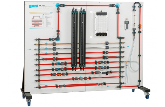
HM 120 allows the investigation by experimentation of pressure losses in pipes and different pipe elements.
The trainer includes ten pipe sections with different pipe elements. Four of the pipe sections are straight and designed with a constant cross-sectional area; they differ from each other in material and cross-section. One of the pipe sections includes three different types of flow diversion: pipe bend, pipe angle and segment bend. Two other pipe sections include various shut-off valves and fittings with different resistances. The opening characteristics of the valves and fittings are determined in the experiment. Two other pipe sections contain gradual and sudden contractions and enlargements. The last pipe section is designed as a parallel, dual line.
A water supply and drain are required for operation. If the trainer is to be operated as a closed circuit without connection to the mains water network, this can be done with the optional HM 130.01 unit.
The pressure measuring points in the pipe system are designed as annular chambers and are located directly upstream and downstream of the pipe elements, ensuring a precise pressure measurement. The sensors are connected in pairs to a differential pressure meter, a manometer panel or twin tube manometers where the respective differential pressure can be read. The flow is displayed on a rotameter.
- investigation of the pressure losses in pipe elements
- comparison of losses in similar components
- different types of pressure measurement
Pipe sections, length: 1000mm
- straight, Cu, diameter: 18x1mm,
- straight, galvanised steel, diameter: ½”
- straight, PVC, diameter: 20×1,5mm,
- straight, PVC, diameter: 32×1,5mm
- section with segment bend, pipe angle, pipe bend
- gradual/sudden enlargement in diameter: from 20 to 32mm
- gradual/sudden contraction in diameter: from 32 to 20mm
- dual line, PVC, diameter: 20×1,5mm
Measuring ranges
- flow rate: 0…1600L/h
- differential pressure:
- differential pressure meter: 0…2000mbar
- twin tube manometer: 1000mmWC
- 6 tube manometers: 340mmWC
- investigation of the pressure losses in pipe elements
- ten different pipe sections
- measurement of pressure losses in valves, changes in pipe direction, straight pipes, contraction/enlargement or parallel lines
- selection of pipe sections via hose connections with quick-release coupling
- operation via mains water network or in a closed circuit with HM 130.01
- flow measurement with rotameter
- pressure sensor in annular chambers
- differential pressure measurement with differential pressure meter or twin tube manometers or 6 tube manometers
- different methods of differential pressure measurements
- influence of pipe diameters, different materials and surface roughness
- effect of the flow velocity
- pressure loss in pipe bends, pipe angles and segment bends
- pressure losses in cross-section changes
- determination of resistance coefficients
- valve characteristics of various valves and fittings
- comparison between experiment and calculation