
HM 260 Characteristics of nozzles
Fluids are accelerated in nozzles, while the pressure decreases. When using compressible fluids (e.g. air) very high speeds can be achieved by this process, often in the supersonic range. Nozzles are used in steam turbines, in injector devices, in supersonic aircraft and rockets. The impact forces or thrust (action or reaction force) occurring in the fluid is referred to when designing the shape of nozzles.
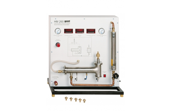
HM 260 offers two experiment layouts for nozzles, in which either the occurring action force or reaction force of the fluid is considered. Characteristics such as flow velocity and nozzle efficiency are measured. In addition, the “choking effect” is demonstrated, where the mass flow stops increasing upon reaching the critical pressure ratio. Air is used as a compressible fluid.
In the first experiment layout to determine the reaction force, a nozzle is inserted into the force measuring device. The force measuring device consists of a bending beam, whose deformation is measured electronically. The air pressure upstream and downstream of the nozzle can be adjusted. Compressed air flows through the nozzle and the occurring reaction force (thrust) of the fluid is measured.
In the second experiment layout, the baffle plate is inserted into the force measuring device and the nozzle is positioned above the baffle plate. The position of the nozzle is adjustable, so that the distance between the nozzle and the baffle plate can be varied. The flow at the nozzle outlet impacts against the baffle plate and the action force (impact force) of the fluid is detected by the deformation of the bending beam.
Pressures and mass flow are also detected in addition to the force. The temperatures are also measured, in order to determine the mass flow precisely. Four convergent-divergent and one convergent nozzle as well as a baffle plate are available for experiments.
- force effects in nozzle flow
- determining the nozzle efficiency
- four convergent-divergent nozzles with different area ratios, one convergent nozzle and one baffle plate
Air consumption of the experimental unit
- compressed air: max. 10bar
- air consumption: approx. 5g/s
5 nozzles, brass
- 4x convergent-divergent
- 1x convergent
- diameter, all nozzles: 2mm
- length, divergent nozzles: 3,6 to 15,8mm
Compressed air regulator
- control range: 0…8,6bar
Measuring ranges
- temperature: 0…100°C
- pressure: 2x 0…10bar
- mass flow rate: 0,7…8,3g/s
- force: 0…2N
230V, 50Hz, 1 phase
230V, 60Hz, 1 phase; 120V, 60Hz, 1 phase
UL/CSA optional
- detect impact force or thrust at nozzle to determine the flow velocity and nozzle efficiency
- experiment layout A: measuring reaction force (thrust) of the fluid at the nozzle
- experiment layout B: measuring action force of the fluid at the baffle plate
- air intake adaptable according to the experiment layout
- distance between baffle plate and nozzle can be adjusted
- compressed air regulator for adjusting the pressure downstream of the nozzle
- needle valve on the flow meter for adjusting the back pressure
- measuring reaction or action force of the nozzle by deformation of the bending beam
- 5 nozzles with different contours (4 convergent-divergent, 1 convergent) and 1 baffle plate
- instruments: manometer and digital temperature display upstream and downstream of the nozzle, as well as rotameter
- determining the critical pressure ratio
- demonstration of the “choking effect”
- determining flow velocity in the narrowest cross-section
- measurement of the reaction or action force of the flowing fluid
- determine nozzle efficiency by thrust