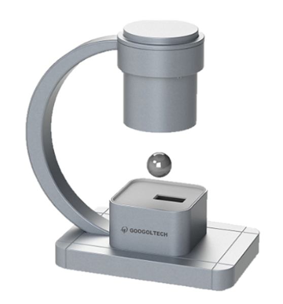
Magnetic Levitation System

The Magnetic Levitation System (MLS) is composed of an LED light source, an electromagnet, an optoelectronic sensor, amplifier module, an analogue control module, data acquisition card, and a steel ball, etc. Its structure is simple, yet the control effect is very intuitional and interesting. One can easily levitate one or more steel balls in a steady-state position and keep them floating. This system synthesizes main experimental contents in control area and satisfies many experiment requirements such as automatic control, control theory, and feedback system, etc, which are suitable for UG or PG course designs and algorithm research as well.
Students can thoroughly comprehend PID tuning, root locus tuning, frequency
domain method tuning, status feedback control method with Matlab software
platform experiment course.
Via optional analog control system, by observing and comprehending the
structure of control system and the characteristic of driving module, students
can construct embedded magnetic levitation controller by combining the
analog control system with DSP, ARM, MCU, etc. The embedded discrete
control algorithm can be perfected by comparing control results.
Students can select components such as photoelectric, ultrasonic, infrared distance detecting sensor to build up the magnetic levitation body; and
construct complete magnetic levitation system with self-designed embedded
controller.
Laser sensor is used as feedback signal. Through the experiments, the
non-linearity of the sys
| Function | Description |
| Winding Resistance | 13.8ohm |
| Control Precision | 0.1mm |
| Winding Turns | 2450 |
| Winding Inductance | 135mH |
| Winding Dimension | Diameter=20 mm , H=94mm |
| LED Light Source | +12V, 1W |
| Sampling Frequency (AD) | 30KHz |
| Power Input | AC220V 50HZ 3A (AC110V Optional) |
| Control Range | 1~20mm (m=22g , diameter =25mm)
1~15mm (steel ball m=120g , diameter =55mm) |
| Data Acquisition Card | – 16 double-ended analogue input channels, 2 single-ended analogue output channels.
– 16 digital input/output channels – 12-bit A/D converter, sampling rate up to 100KHz – 1K sampling FIFO buffer on-board – Each input channel gain programmable – Automatic channel /gain scan – Analogue sampling channel voltage range selectable (+10V , +5V , +2.5V , +1.25V , +0.625V) |
| Dimensions | 350mm x 178mm x 376mm |
| Weight | <10Kg |
● PID Correction
● Root Locus Correction
● Frequency Domain Correction
● State Feedback Control
● Mechanism Modelling and Stability Analysis

