RC filters
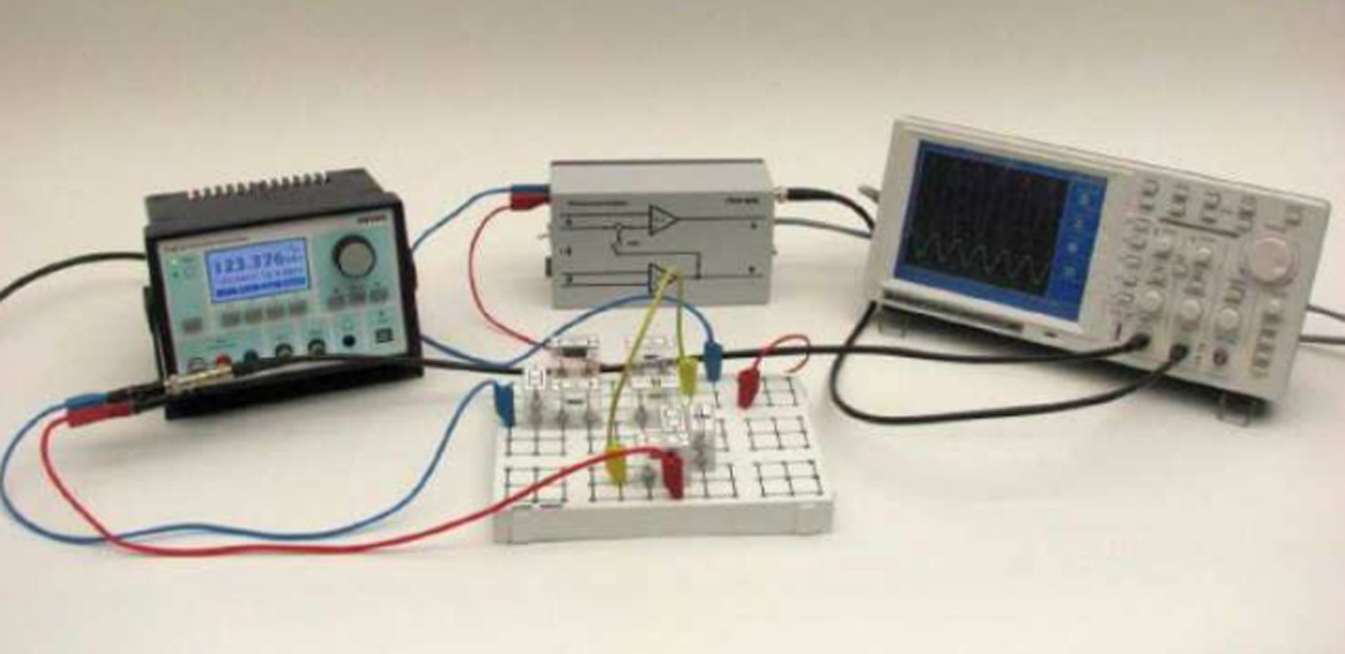
Resistor-Capacitor (RC) circuits serve as filters for frequencies. The frequency response of the most commonly used RC filters is recorded by point-by-point measurements as well as the frequency sweep method, and displayed on the oscilloscope. The results are plotted and verified using the measure analysis software.
- Investigate several types of frequency filters
- High-resistance inputs of the difference amplifier allow measurements without influencing the electrical behaviour of the circuit
- Easy frequency setting thanks to digital function generator
Difference amplifier
30 MHz digital storage oscilloscope with colour display,2 x BNC cables l = 75 cm incl.
PHYWE Digital Function Generator, USB
Resistor 1 kOhm, 1W, G1
Capacitor 10nF/ 250V, G1
Short-circuit plug, white
Plug-in board, for 4 mm plugs
Resistor 500 Ohm 5%, 1W, G1
Connecting cord, 100 mm, yellow
Connecting cord, 32 A, 500 mm, red
Connecting cord, 32 A, 500 mm, blue
Screened cable, BNC, l = 750 mm
Screened cable, BNC, l 1500 mm
Connector, T type, BNC
Adapter, BNC-plug/socket 4 mm
- Record the frequency response of the output voltage of
- a high-pass filter
- a low-pass filter
- a band-pass filter
- a Wien-Robinson bridge
- a parallel-T filter, point by point and to display the sweep on the oscilloscope. Investigate the step response of
- a differentiating network
- an integrating network.
2. Analyse and verify the measurements using the measure analysis software.
- High-pass
- Low-pass
- Wien-Robinson bridge
- Parallel-T filters
- Differentiating network
- Integrating network
- Step response
- Square wave
- Transfer function