Rectifier circuits
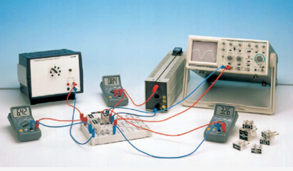
The ripple of the output voltage of various rectifier circuits is measured as a function of the load current strength and the charging capacitance. The characteristics of a voltage stabilizer and of a multiplier are investigated.
- Get to know several types of rectifier circuits
- Suitable for vocational classes
30 MHz digital storage oscilloscope with colour display,2 x BNC cables l = 75 cm incl.
PHYWE multitap transformer
Resistor 470 Ohm, 1W, G1
Resistor 47 Ohm, 1W, G1
Electr.capaci. 470 microF/35V,G1
Electrol.capacitor10microF/35V,G1
Semiconductor diode Si, 1 N 4007, case G1
Electrolyte capacitor 2000 µF/35V, G2
Low power zener diode ZF 4,7, G1
Short-circuit plug, white
Plug-in board, for 4 mm plugs
Capacitor,electr.1mF/35V,G1
Rheostat, 330 Ohm , 1.0A
Digital multimeter 2005
Connecting cord, 32 A, 250 mm, red
Connecting cord, 32 A, 250 mm, blue
Connecting cord, 32 A, 500 mm, red
Connecting cord, 32 A, 500 mm, blue
Adapter, BNC-plug/socket 4 mm
- To display the output voltage (without charging capacitor) on the oscilloscope.
- To measure the diode current I_d as a function of the output current strength I_0 (with the charging capacitor).
- To measure the ripple component U_ACpp of the output voltage as a function of the output current (C=constant).
- To measure the ripple as a function of the capacitance (I_0=constant).
- To measure the output voltage U_0 as a function of the input voltage U_i (I_0=0).
- Half-wave rectifier
- Full-wave rectifier
- Graetz rectifier
- Diode and Zener diode
- Avalanche effect
- Charging capacitor
- Ripple
- r.m.s. value
- Internal resistance
- Smoothing factor
- Ripple voltage
- Voltage stabilisation
- Voltage doubling