RLC circuit with Cobra4 Xpert-Link
In an RLC circuit, energy is exchanged periodically between a capacitor and a coil. When the electric field of the capacitor decreases by discharge over the coil, a magnetic field is established in the coil. As soon as the capacitor is completely depleted, the current flow through the coil vanishes. The magnetic field decreases again and the capacitor is charged, again. If this process could run loss-free, the energy would oscillate continuously between capacitor and coil with the resonance frequency, that is depending on the used components. The circuit is called RLC circuit because of the crucial physical properties, the inductance L of the coil, and the capacitance C of the capacitor.
- Voltage and current can be measured directly and simultaneously
- Root mean square value displayed in real-time
- Impedance will be computed in real-time
- Fast and easy experimenting simply by switching components
- Cost savings: oscilloscope functions integrated into the datalogging solutionf
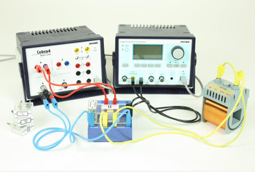
PHYWE Digital Function Generator, USB
Resistor 470 Ohm, 1W, G1
Resistor 47 Ohm, 1W, G1
Resistor 100 Ohm, 1W, G1
Capacitor 10nF/ 250V, G1
Capacitor 47nF/ 250V, G1
Capacitor 100 nF/250V, G1
Capacitor 470nF/250V, G1
Connection box
Coil, 900 turns
Cobra4 Xpert-Link
Cobra4 Xpert-Link set of cables
- Measure the voltage drop over the LC component and the current through the circuit of a series-tuned and a parallel-tuned RLC circuit and determine the resonance frequencies.
- Determine the impedance of the various RLC circuits.
- Determine the bandwidth and the Q-factor from the resonance curves of the respective RLC circuit.
- Periodic oscillations
- Damped oscillations
- Forced oscillations
- Kirchhoff’s laws
- Series-tuned circuit
- Parallel-tuned circuit
- Resistance
- Capacitance
- Inductance
- Reactance
- Impedance
- Phase shift
- Q-factor
- Bandwidth