
SE 110.17 Three-hinged arch
Bridges are often constructed as three-hinged arches. This type of construction is particularly suitable when compression-proof building materials are available. Horizontal thrust occurs in the arch at the supports. It permits much lower bending moments in the arch than in the case of a beam on two supports with the same span. A significant longitudinal compressive force is active in the arch to produce this effect.
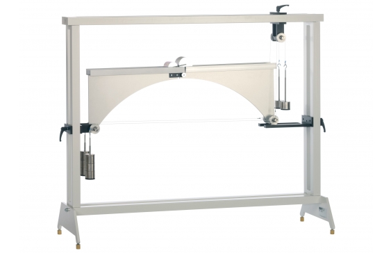
A three-hinged arch consists of a curved beam mounted on two fixed supports, and usually featuring the so-called crown hinge at its crown. The hinges on the two fixed supports absorb vertical and horizontal forces, and are known as abutment hinges. Their connecting line is the springing line. The crown hinge renders the system statically determinate.
SE 110.17 includes two long arch segments and one short segment, of which two at a time are connected by a hinged joint producing a symmetrical or unsymmetrical three-hinged arch. The arch under investigation can be subjected to point, distributed or moving load. Weights compensate for the support reactions of a abutment hinge, so enabling a comparison between calculated and actual measured values.
All the component elements of the experiment are clearly laid-out and housed securely in a storage system. The complete experimental setup is arranged in the frame SE 112.
- statically determinate three-hinged arch
- symmetrical or unsymmetrical arch
- various load cases: point load, distributed load, moving load
Aluminium arches
- 2x long: 480mm, total arch length: 960mm
- 1x short: 230mm, total arch length: 710mm
- arch height: 250mm
Weights
- 4x 1N (hanger)
- 36x 1N
- 16x 5N
- moving load: 10N+20N
- investigation of 2 statically determinate three-hinged arches
- hinged arch with 3 hinges: 1 crown hinge, 2 abutment hinges at the support points
- 3 arch segments: 2x long (together making a symmetrical arch), 1x short (together with 1x long: unsymmetrical arch)
- arch subjected to point load, distributed load (each by loads) or moving load
- loads to compensate for the support reactions of an abutment hinge
- storage system to house the components
- experimental setup in frame SE 112
- familiarisation with three-hinged arches (unsymmetrical and symmetrical)
- application of the method of sections and the conditions of equilibrium to calculate the support forces for
- point load, distributed load, moving load
- investigation of the influence of the load on the horizontal thrust in the supports
- determination of the lines of influence for the supports under a moving load
- comparison of the calculated and measured support reactions for static and moving load