
SE 110.18 Forces on a suspension bridge
Suspension bridges are among the oldest of all bridge designs. Their main supporting element is a flexible cable. Since cables are able to absorb high tensile forces while themselves having little dead-weight, they enable wide-span suspension bridges to be constructed. This makes it possible to bridge longer distances with no supporting pillars, such as over wide gorges. The sag of suspension bridge supporting cables is parabolic in shape, as the weights are attached at relatively short, constant intervals by way of vertical cables to the main supporting cables.
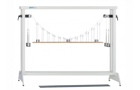
The experimental setup SE 110.18 represents a suspension bridge. The bridge consists of two parallel supporting cables with a roadway suspended between them. U-shaped hangers serve as vertical cables. They are attached to the main supporting cables at regular intervals, and hold the roadway. Deflection rollers act as pylons. The roadway acts upon the supporting cables as a distributed load, and can be loaded by additional weights.
Two roadways with different stiffness are available: one stiff and one elastic roadway. The stiff roadway has a hinge in the middle. The hinge permits internal moments in the roadway occurring in response to uneven loading to be visualised – the roadway buckles.
The experimental setup without roadway deals with free-hanging cables. Cables with different dead-weights are studied by attaching additional point loads directly to the supporting cables.
The tensile forces in the supporting cables are determined with the aid of weights. The maximum sag is measured using a scaled rule. The scaled rule is fixed to a cross-arm.
All the component elements of the experiment are clearly laid-out and housed securely in a storage system. The complete experimental setup is arranged in the frame SE 112.
- stiff or elastic roadway for the suspension bridge
- different load cases possible: point or distributed load
- catenary of a free-hanging cable
Suspension bridge
- span: approx. 1050mm
- supporting cable sag: approx. 325mm
- number of supporting cables: 2
- shackles: 12, graduated lengths
Stiff roadway, two-section with hinge, wood
- LxWxH: 1000x70x10mm
- dead-weight of roadway: 5,5N
Elastic roadway, PVC
- LxWxH: 1000x70x3mm
- dead-weight of roadway: 3N
Weights
- 16x 1N (hanger)
- 12x 1N (shackle)
- 24x 1N
- 28x 5N
- investigation of a suspension bridge in various load cases
- suspension bridge, consisting of 2 supporting cables, roadway and 2 deflection pulleys as pylons
- supporting cables with parabolic sag
- hangers (vertical supporting cables) in the form of U-shaped shackles in graduated lengths
- roadway (distributed load) can be loaded by additional weights
- 2 selectable roadways: stiff roadway (two-section with central hinge) and elastic roadway
- experimental setup “hanging cable”: supporting cables without roadway, loaded with point loads
- 4 hanger to measure the cable force in both supporting cables
- storage system to house the components
- experimental setup in frame SE 112
- familiarisation with a suspension bridge
- under dead-weight
- under additional weight
- under evenly distributed load
- under unevenly distributed point loads
- calculation of the supporting cable force
- comparison between calculated and measured values of the supporting cable force
- observation of the effect of internal moments in the roadway under uneven load
- for a stiff roadway
- for an elastic roadway
- determination of the catenary of a free-hanging cable